Traditional Yard and Pool Gate
Before You Begin
- Read your Traditional Yard & Pool Fence install guide first — your gate and fence will work better together once you understand how the fence goes in.
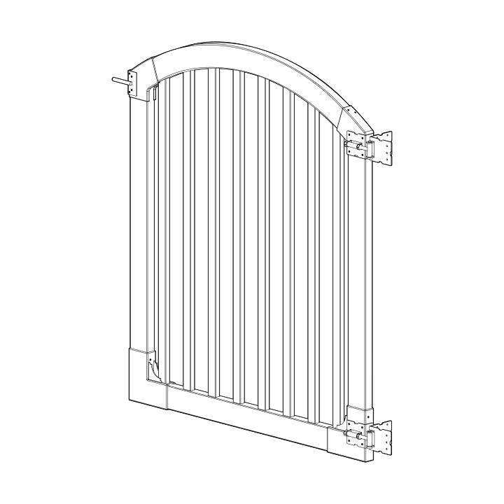
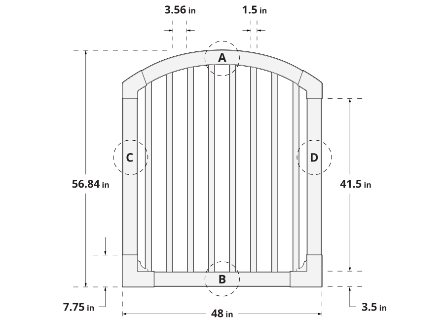
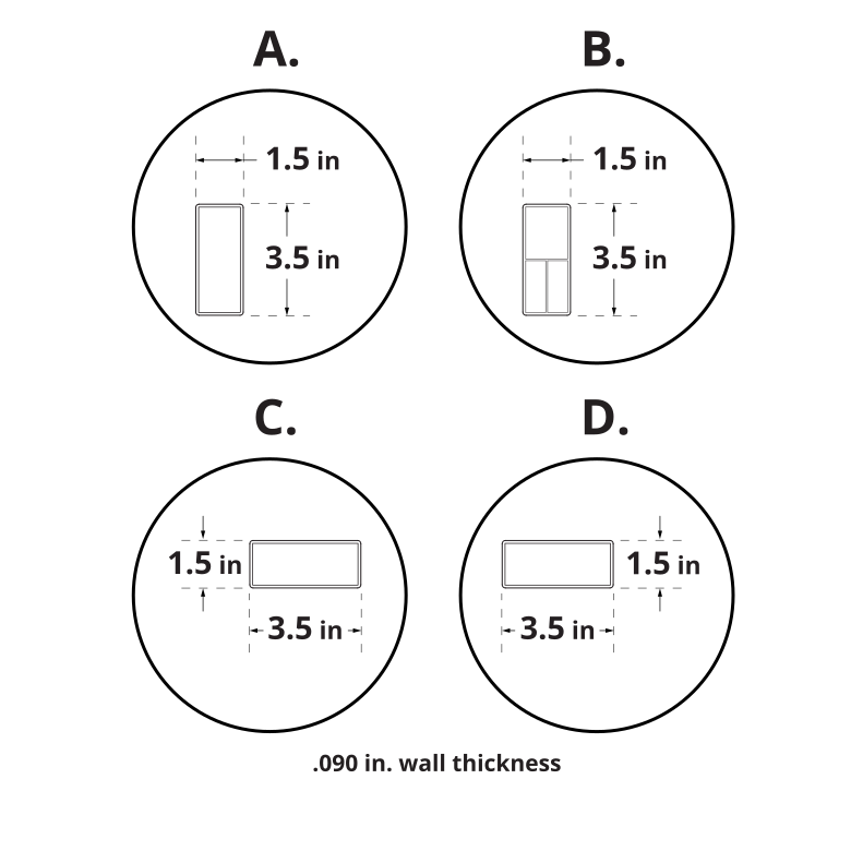
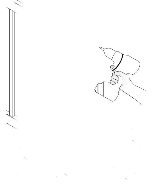
- Dry-fit the gate frame before you drive a single screw. A dry run confirms every piece is in the box, that you have the assembly order right, that everything fits and functions, and that your gate matches the measurements shown in the specifications below. Troubleshooting is far easier before anything is screwed together — take the frame back apart as needed, then reassemble it permanently with the 1¼in self-drilling stainless steel screws.
- Position and install your gate posts before your fence posts. Fence panels are more forgiving of a custom fit than a gate is.
- Call 811 before you dig to check for underground utilities — this gate needs two finishing posts set into the ground. In the US call 811 or visit www.call811.com; in Canada visit clickbeforeyoudig.com.
- Check local zoning laws and HOA rules — height, style, and placement may be regulated, and some locations require a permit.
- Confirm the installation falls inside your property limits, and talk to your neighbors before you start.
- Check the inside of the larger pieces in your box for other materials packed inside.
- Assemble components on a non-abrasive surface, such as the shipping box, to avoid scratching.
- Allow an area of roughly 5ft x 8ft for unobstructed assembly.
- You should not need to use excessive force when assembling components.
Returns: Please let us help resolve any issues before initiating a return. If a return is still necessary, it must be initiated with the retailer where the product was purchased.
Need Help or Replacement Parts?
Our US-based customer service team is available Monday–Friday, 9am–5pm EST.
- Parts Website: https://parts.nychbrands.com
- Email: hmmm@wambamfence.com
- Phone: 704-892-5222 or 877-778-5733
- Text: 704-892-5222
For faster service, have your item number (VG13005) and part name ready. A batch lot number (found on the end of the box) is also helpful — it assists us in identifying and resolving any production issues.
Buying Guide
Product Specifications & Dimensions
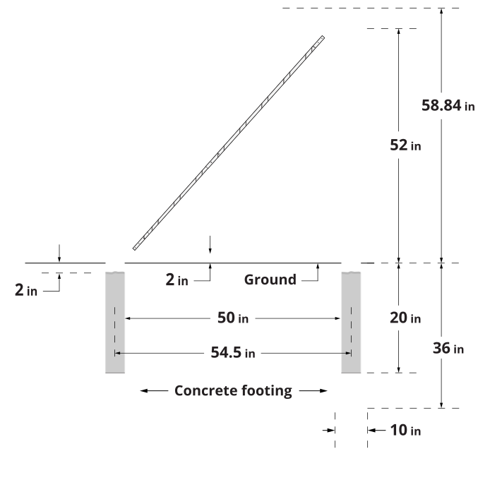
Pool Code Notes
For swimming and other child-safety gates, most safety standards specify that your fence height be between 4ft and 6ft high minimum, that your gate open outward away from the pool, and that the latch-releasing mechanism sit a minimum of 54in from the ground.
The Yard & Pool Gate requires a specialized latching system to meet pool code. Use MagnaLatch Top Pull Hardware (not included) — Magna Latch Top Pull Code # MLTPS2BGA.
Always confirm these and other requirements with the appropriate authorities in your area. Code varies from one location to another across the country.
Gate Brace Warning
The gate brace included with this gate may be considered a climbing surface by some pool inspectors and, therefore, in conflict with pool code. This gate can be assembled and installed without the brace, if necessary.
Hinge Post Support
Do not hang your gate off a single unsupported post. Your gate will perform better and last longer when its hinge post is connected to a panel of fence that is connected to another post — that way the weight strain is carried by two posts instead of one. Installing fence panels on both sides of your gate is ideal in all situations. If space restrictions make this impossible, contact us for alternative solutions.
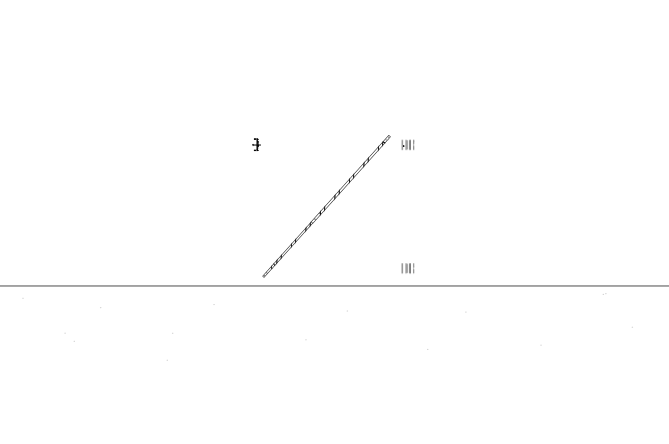
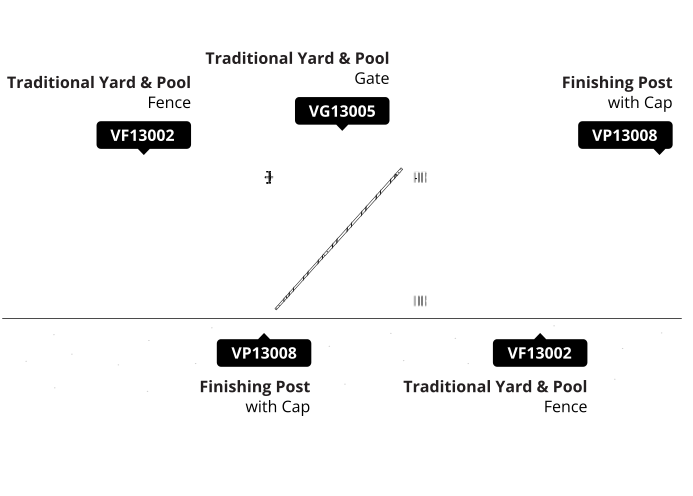
Finishing Post: VP13008
Gates do not come with their own posts
You will need two finishing posts — a VP13008 (2 pack) — one to support the gate, and one to finish the fence run.
Required Tools
Safety Glasses
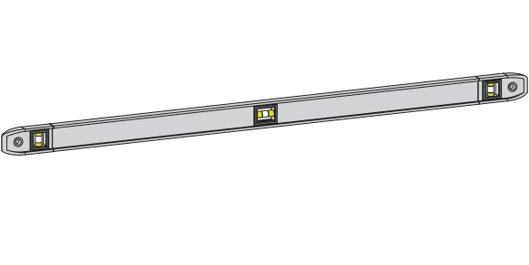
1ft Torpedo Level
4ft Level (a string line level also works)
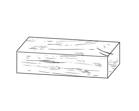
Wood "Spacer" Blocks (2)
2in x 2in x 6in
Cordless Drill (preferably with a high-torque setting)
Shovel
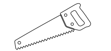
Power or Hand Saw with a Fine-Toothed Blade
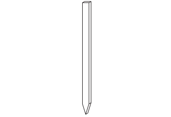
String Line Stakes
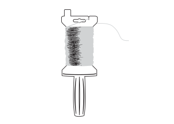
Spool of String
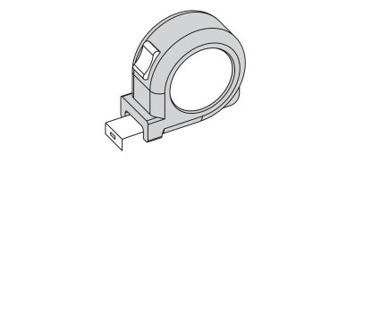
Tape Measure
Concrete (purchased separately)

Part Identification
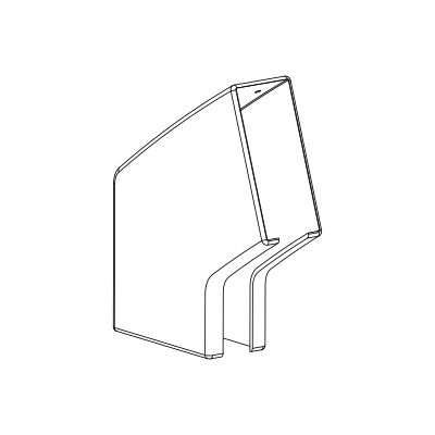
A
Arch Bracket (2)
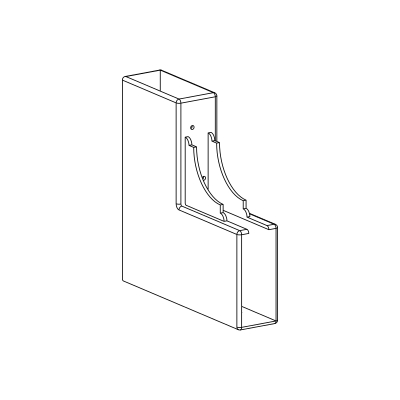
B
Corner Bracket (2)
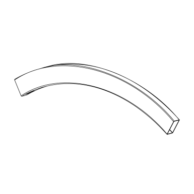
C
Top Rail (1)
1½in x 9in x 42¼in
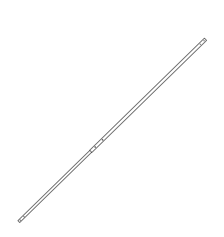
D
Gate Brace (1)
E
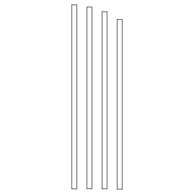
Pickets (8)
Picket 1 (2) ⅞in x 1½in x 54¼in
Picket 2 (2) ⅞in x 1½in x 53½in
Picket 3 (2) ⅞in x 1½in x 52⅛in
Picket 4 (2) ⅞in x 1½in x 50in
F
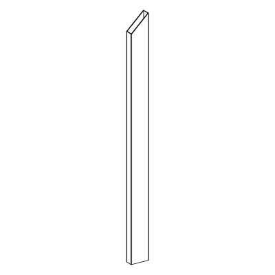
Vertical Stile (2)
1½in x 3½in x 45in
G
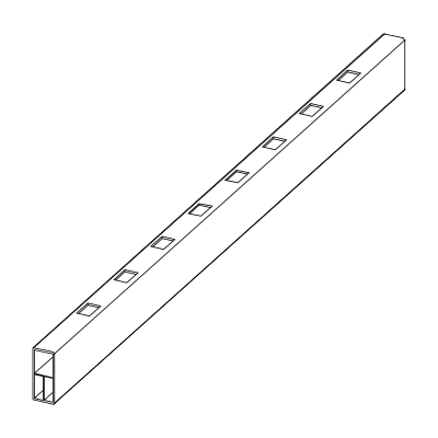
Bottom Rail (1)
1½in x 3½in x 47¾in
H
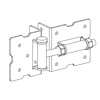
Gate Hinge with Screws (2)
I
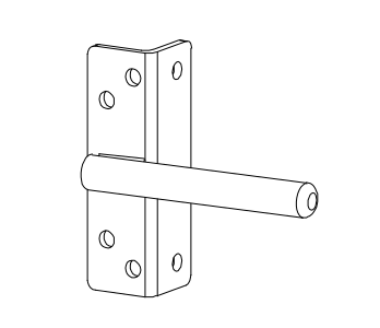
Latch Finger (1)
J
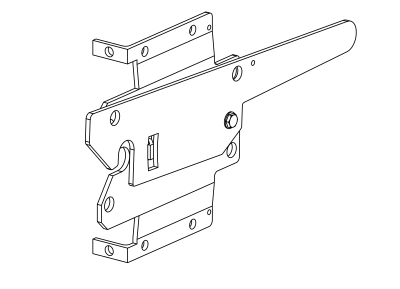
Latch Catch (1)
K
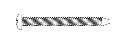
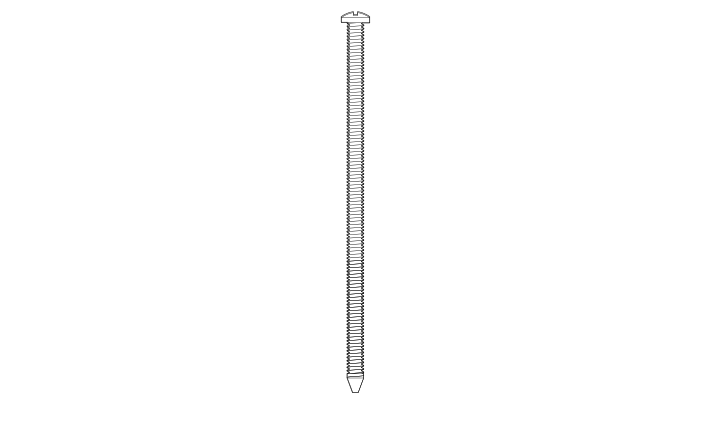
1¼in White Self-Drilling Stainless Steel Screw (20)
L
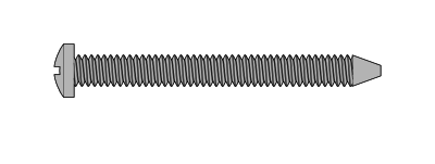
1¼in Black Self-Drilling Stainless Steel Screw (24)
M
2in Black Self-Drilling Stainless Steel Screw (14)
N
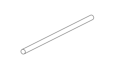
4in Tension Pin (2)
Step 1: Assemble the Frame Bottom and Sides
Parts Required
G x1 B x2 F x2
Insert the bottom rail (G) fully into the first corner bracket (B) until it bumps up against the corner of the bracket, then insert the opposite end into the second corner bracket (B) the same way.
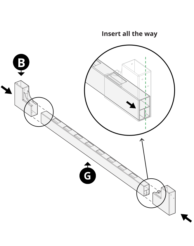 Note: The bottom rail is ribbed internally.
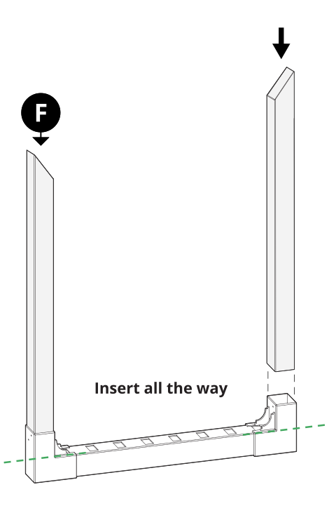
Insert the vertical stiles (F) into the corner brackets; they will bottom out against the bottom rail.
Step 2: Assemble the Gate Arch
Parts Required
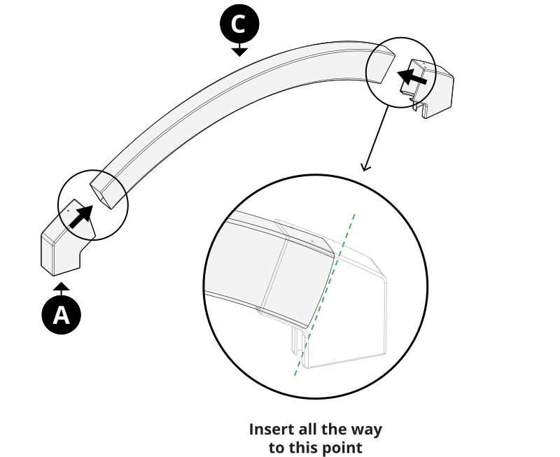
A x2 C x1
Insert the top rail (C) into the arch brackets (A) on both ends, pushing each end all the way to the seating point shown.
Step 3: Insert the Pickets
Parts Required
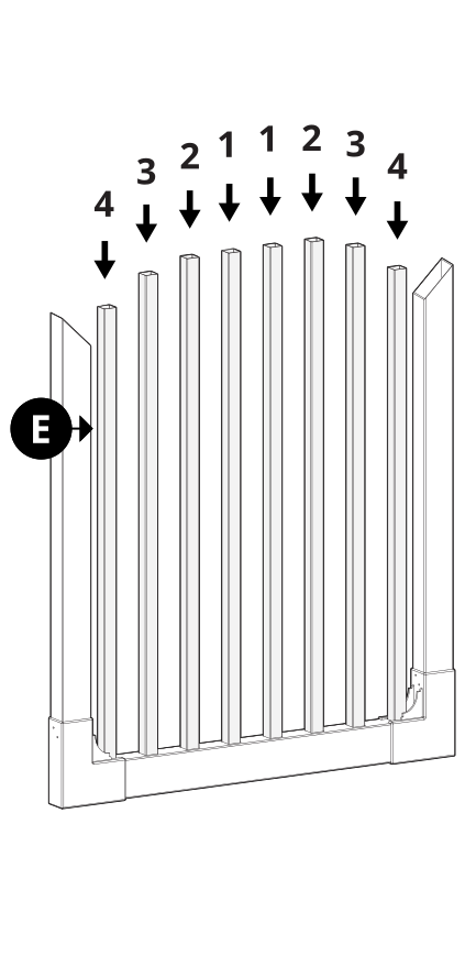
E x8
Insert pickets 1, 2, 3, and 4 (E) through the holes in the bottom rail in the graduated pattern shown — 4, 3, 2, 1, 1, 2, 3, 4 from one side to the other.
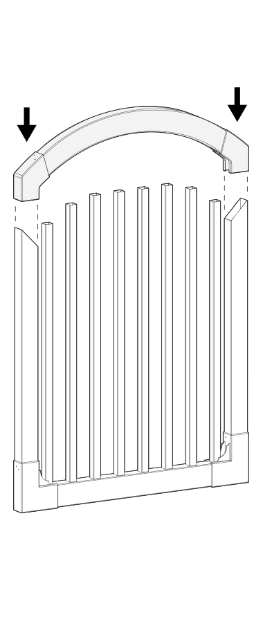
Slide the gate arch assembly down over the pickets and vertical stiles.
Step 4: Square and Secure the Frame
Parts Required
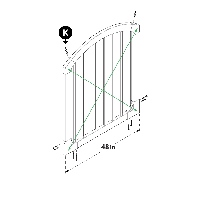
K x12
Make sure your gate is square — the corner-to-corner measurements should match and the gate should measure 48in wide. Secure the brackets using (12) 1¼in white self-drilling stainless steel screws (K) as illustrated.
Step 5: Fasten the Hinges and Latch
Parts Required
I x1 H x2 L x18
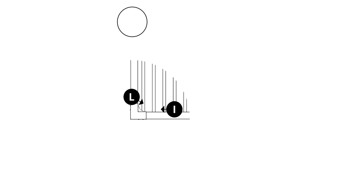
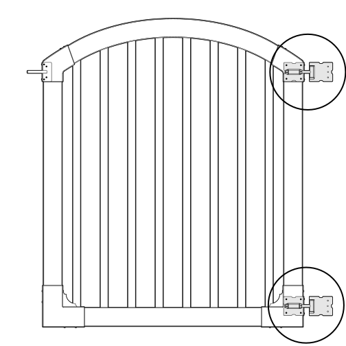
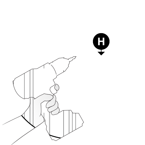
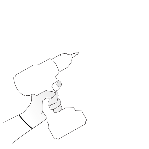
Fasten the latch finger (I) onto the arch bracket using (6) 1¼in black self-drilling stainless steel screws (L). Then fasten the gate hinges (H) onto the opposite arch bracket and bottom bracket using (12) more of the black screws (L), for (18) in total.
Step 6: Assemble and Fasten the Gate Brace
Parts Required
D x1
Assemble the gate brace (D) by sliding the larger square tube over the smaller square tube. Align the holes and install using the included hardware.
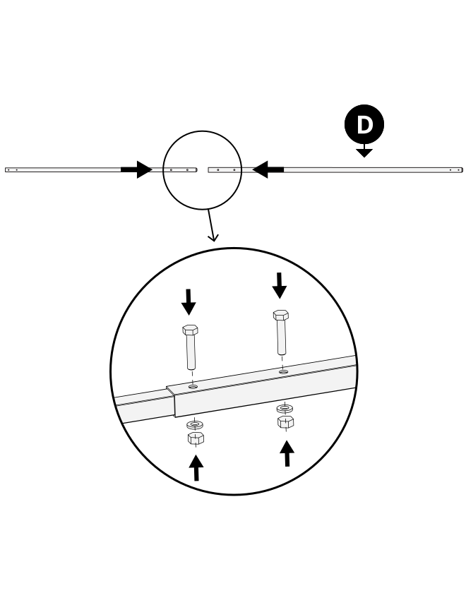
Double-check that the gate is square, then screw the brace into place using the (4) self-drilling stainless steel screws packaged with the gate brace.
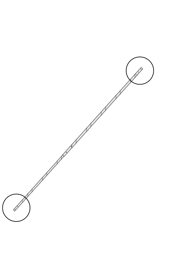
Step 7: Align the Gate and Secure the Hinges
Parts Required
M x6
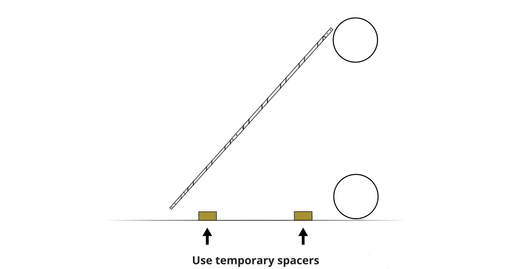
Use the wooden blocks as temporary spacers to rest the gate on during alignment and installation. Fasten the gate hinges to the posts using (6) 2in black self-drilling stainless steel screws (M).
Step 8: Level the Gate and Adjust the Hinges
Parts Required
M x8 N x1
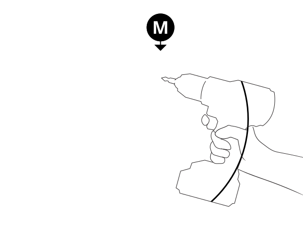
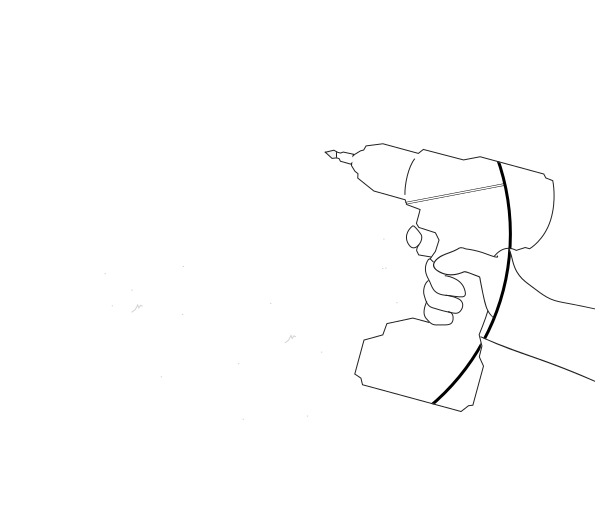
Fasten the gate hinges to the inside of the post using (8) 2in black self-drilling stainless steel screws (M) as illustrated.
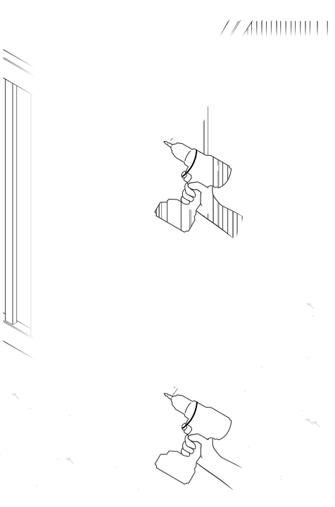
Using a level, make sure the gate fits and functions properly with its latching post.
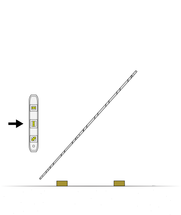
The hinges can be adjusted moderately to level the gate's alignment with the post by using two wrenches to loosen or tighten the nuts on the hinges.
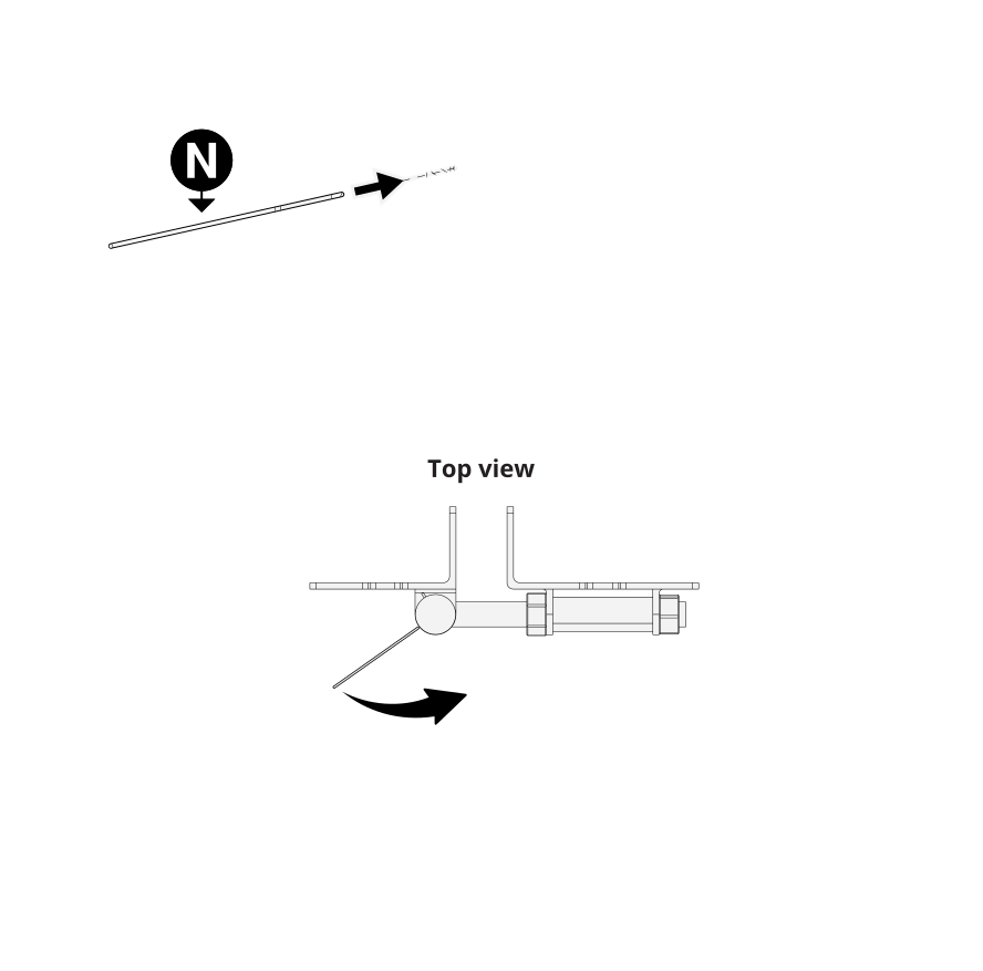
 Note: Adjust the spring tension in the hinges as necessary, using the 4in tension pin (N).
Step 9: Install the Gate Latch
Parts Required
J x1 L x6
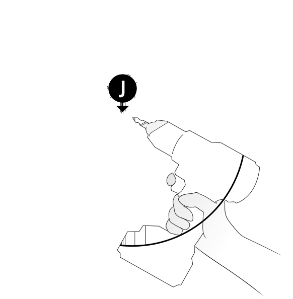
Align and fasten the latch catch (J) to fit and function with the latch finger, using the (6) remaining 1¼in black self-drilling stainless steel screws (L).
Need Help?
- Email: hmmm@wambamfence.com
- Phone: 704-892-5222 or 877-778-5733
- Text: 704-892-5222
