Cambridge Vinyl Fence Panel w/ Post
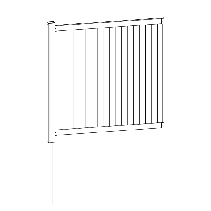
Before You Begin
- Before driving the pipe anchor, check for underground utilities. In the US, call 811 or visit www.call811.com. In Canada, visit www.clickbeforeyoudig.com to find your provincial one-call centre.
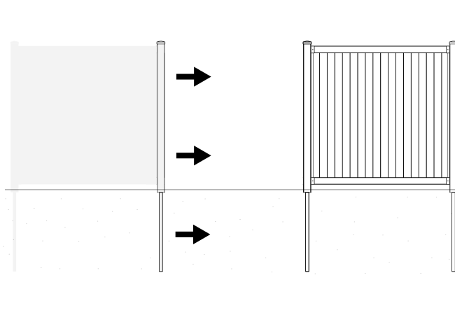
- Build one complete panel first — there is a learning curve. After one panel is installed, it is most efficient to drive all remaining pipes, then build panels onto the posts.
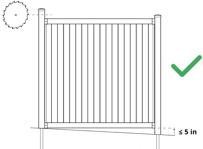
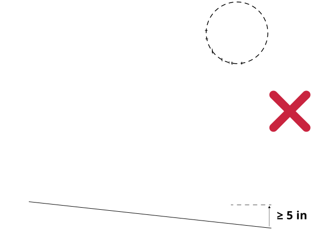
- If your yard slope exceeds approximately 4–5" per 6' panel, you will need to split your panel and purchase an extra post and brackets.
Returns: Please let us help resolve any issues before initiating a return. If a return is still necessary, it must be initiated with the retailer where the product was purchased.
Need Help or Replacement Parts?
Our US-based customer service team is available Monday-Friday, 9am-5pm EST.
- Website: https://parts.nychbrands.com
- Email: hmmm@wambamfence.com
- Phone: 704-892-5222 or 877-234-6196
For faster service, have your item number (BL19110) and part name ready. A batch lot number (found on the end of the box) is also helpful if available — it helps us identify and resolve any production issues on our end.
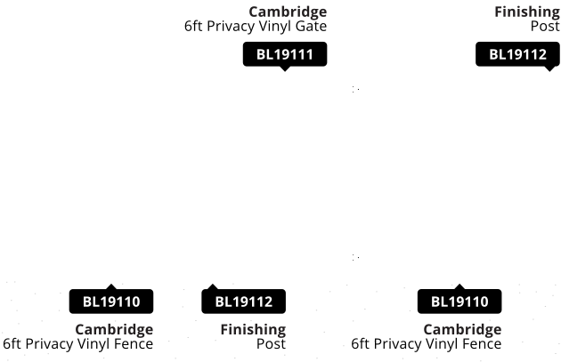
Finishing Post: BL19112
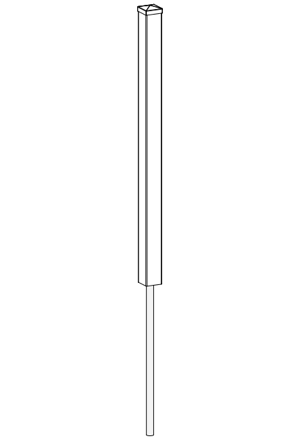
Your panel comes with 1 post/anchor kit. You will need 1 Finishing Post (BL19112) to finish the fence run. If you are installing a Gate (BL19111), you will need two finishing posts — one to finish the run, and one to support the gate.
Buying Guide
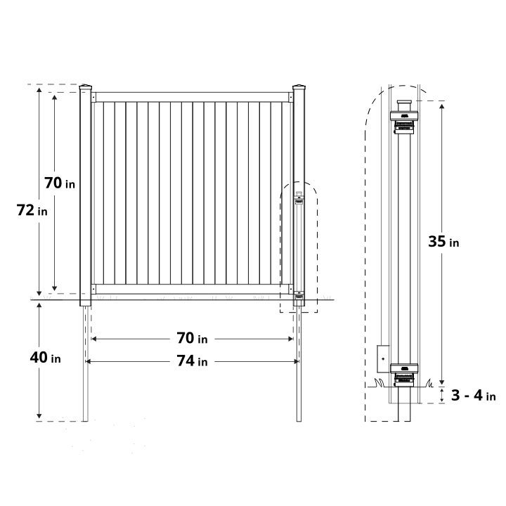
Product Specifications & Dimensions
Post Pounder Considerations
Pounders can be purchased/rented at your local hardware store, or on our website. For safety reasons, we do not recommend using a sledgehammer.
Good
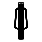 Small Post Pounder
12–18 lbs.
Small Post Pounder
12–18 lbs.
Best for projects with fewer than 10 pipes.
Better
Large Post Pounder
20+ lbs.
Best for 10+ pipes, and may require two people for smoothest operation.
Best
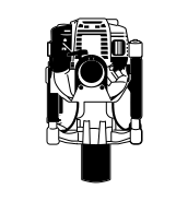 Gas Powered Post Pounder
Rentals are ideal for larger projects. Significantly reduces time and effort required.
Note:
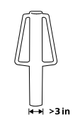
Choose a post pounder with a barrel diameter of 3" or greater. Pounder barrel cannot be longer than 24in.
Required Tools
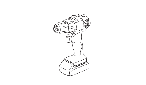
Drill with 2" Bit
Measuring Tape
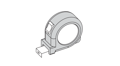
Stakes (Stringline)
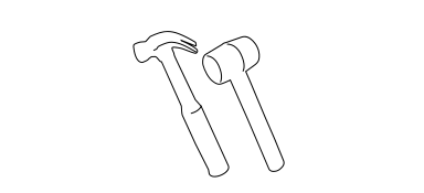
Hammer/Mallet (optional)
Stringline Reel

Pencil

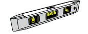
Large Level
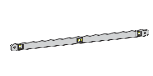
Small Level (for pipe pounding)
Part Identification
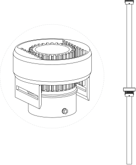
A
Pipe Anchor (1)
1⅝" Diameter × 78½" L
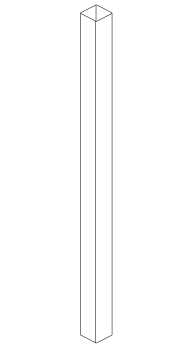
B
Post (1)
4" × 4" × 76"
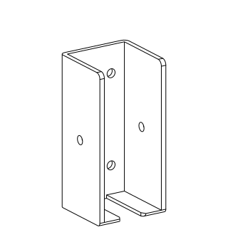
C
Bracket (4)
D
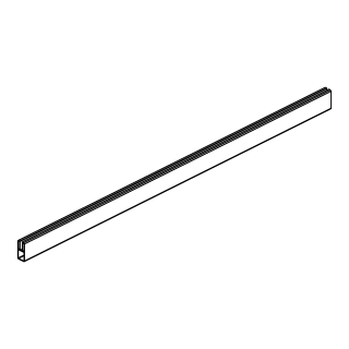
Rails (2)
1½" × 3½" × 69¾"
E
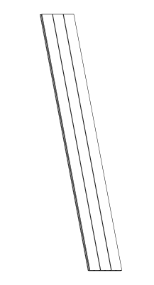
Board (6)
½" × 12" × 66⅜"
F
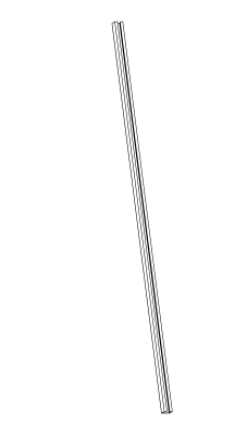
Channel (2)
1½" × 1" × 62⅞"
G
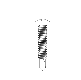
1" Self-Drilling Stainless Steel Screw (34)
H
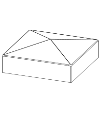
Post Cap (1)
Practice Makes Perfect
Start with one full panel — it's the best way to learn the process. After it's installed, it's most efficient to drive all remaining pipes, then build the rest of the panels onto the posts.
Important: Check for underground utilities before you start driving your pipes!
In the US, call 811 or visit www.call811.com. In Canada, visit www.clickbeforeyoudig.com to find your provincial one-call centre.

Step 1: Determine Slope
Check your yard's slope before you begin.
If the elevation change is under approximately 4–5" per 6' panel, no extra posts are needed — trim the post top to follow the grade once the panel is built.
If the slope exceeds that, you'll need to split your panel: purchase an extra post and set of brackets before continuing.
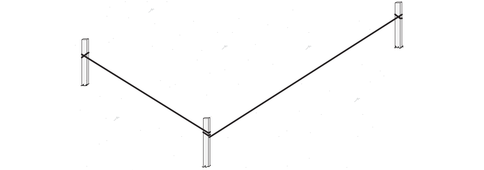
Step 2: Set Stringline
Place a stake at each end of every fence run and tie string between them. Your pipes will be driven according to this line.
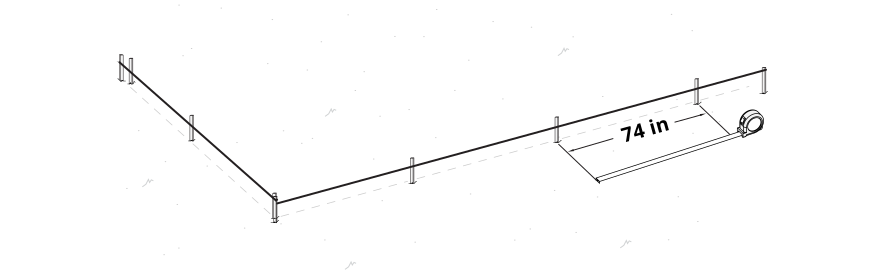
Step 3: Mark Pipe Locations
Use loose stakes or mark the ground every 74" to determine exact pipe locations. Measurements should be taken from center of pipe to center of pipe.
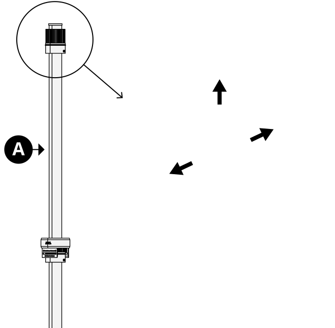
Step 4: Remove Outer Donut
Parts Required
A x1
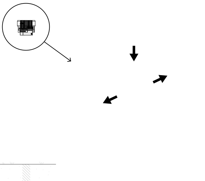
Remove the top donut by pulling the tabs to unlock and lifting it off.
Step 5: Install Pipe Anchors
Parts Required
A x1
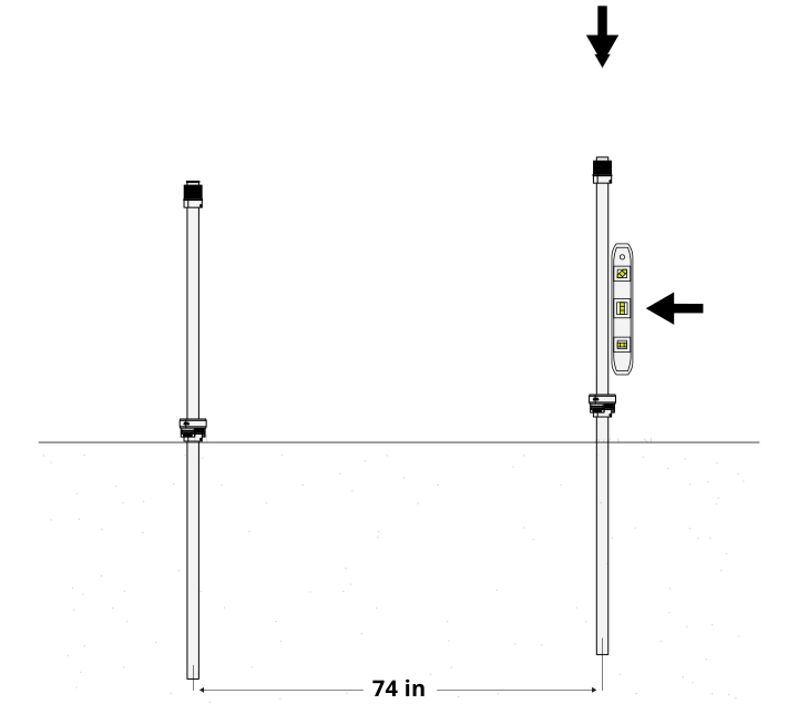
Drive Pipe Anchor (A) into the ground, checking for level roughly every 6" — pound equally from all four sides to help maintain level. Continue until the lower gear touches the ground. Center of pipe to center of pipe: 74".
Step 6: Install Donuts
Parts Required
A x1
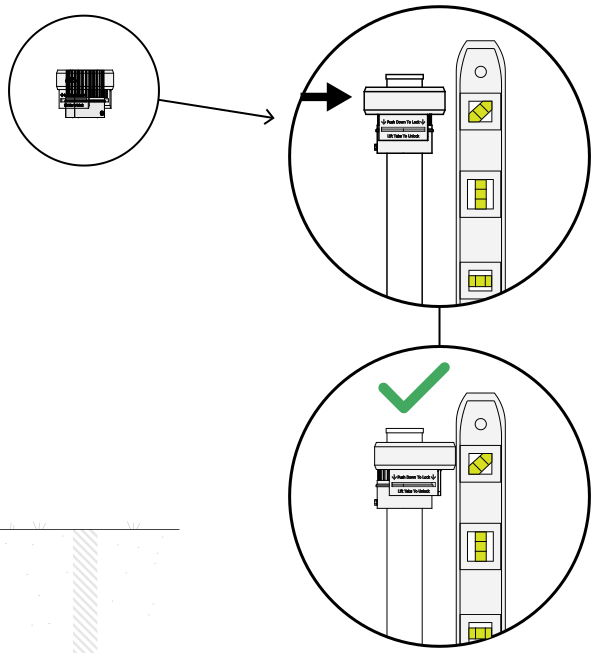
Install the top donut onto each pipe, one at a time, after both pipes are in the ground. Check for level, and use the donut tabs to adjust and compensate for a crooked pipe.
Step 7: Install Posts
Parts Required
B x1
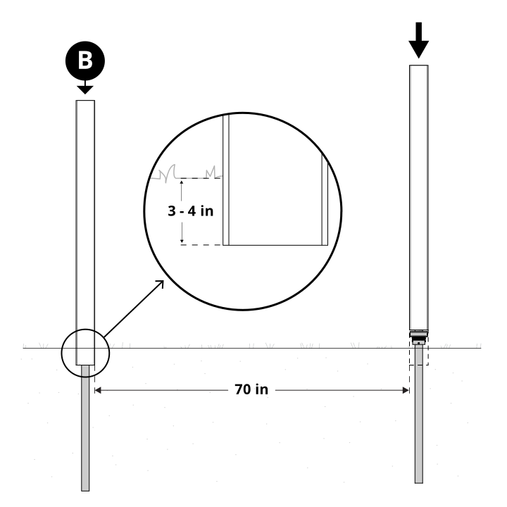
Slide Post (B) down over the pipe. On flat ground, bury posts 3–4" and compact soil around them for stability. Inside of post to inside of post should measure 70".
Step 8: Bracket Installation
Parts Required
C x1 G x4
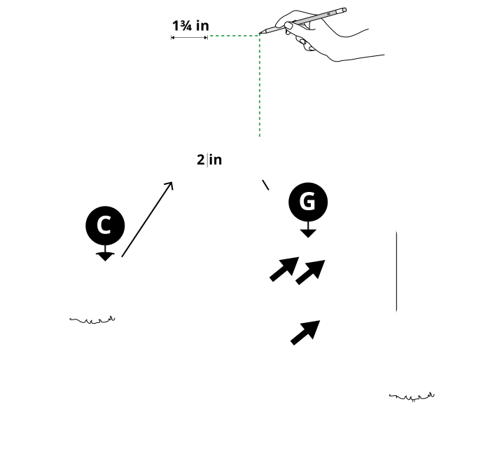
Measure, mark, and secure the first Bracket (C) to your first post using 4 screws (G). The bracket sits 2" off the ground, offset 1¾" from the edge of the post.
Step 9: Bracket Alignment
Parts Required
C x1 D x1
Without driving screws, place a second Bracket (C) over the opposite end of Rail (D) and rest it against the bracket installed in Step 8. Using a level, mark the location of the second bracket on the opposing post, then remove the rail.
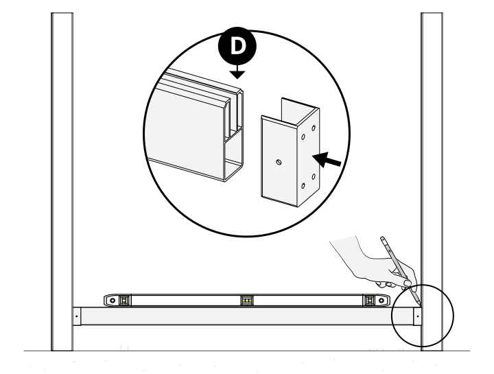
Step 10: Bracket Installation (Second Post)
Parts Required
G x4
Using your marked location, secure the second Bracket to the post with 4 screws (G).
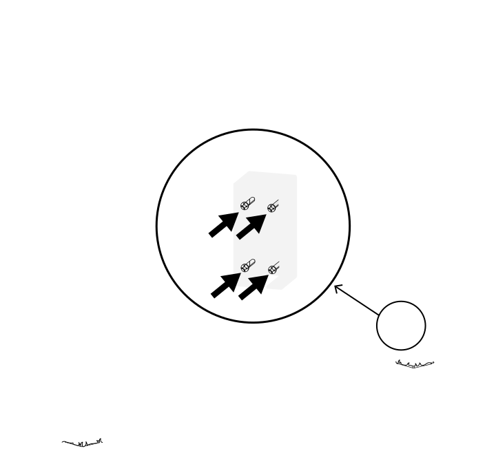
Step 11: Bottom Rail Install
Parts Required
D x1 G x4
Secure bottom Rail (D) into the brackets with 4 screws (G).
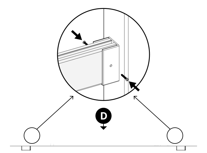
Step 12: Top Bracket Installation
Parts Required
C x2 F x2 G x16
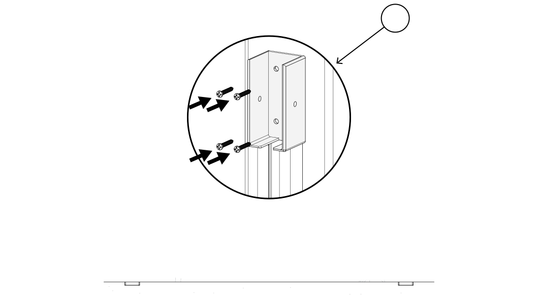
Center and install each Channel (F) on the post using 3 screws (G) per channel. Repeat for the second post. Align the top Brackets (C) flush on top of the channels and secure with 8 screws (G) total.
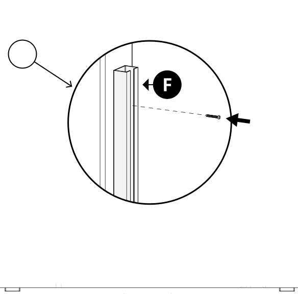
Step 13: Board Infill Installation
Parts Required
E x6
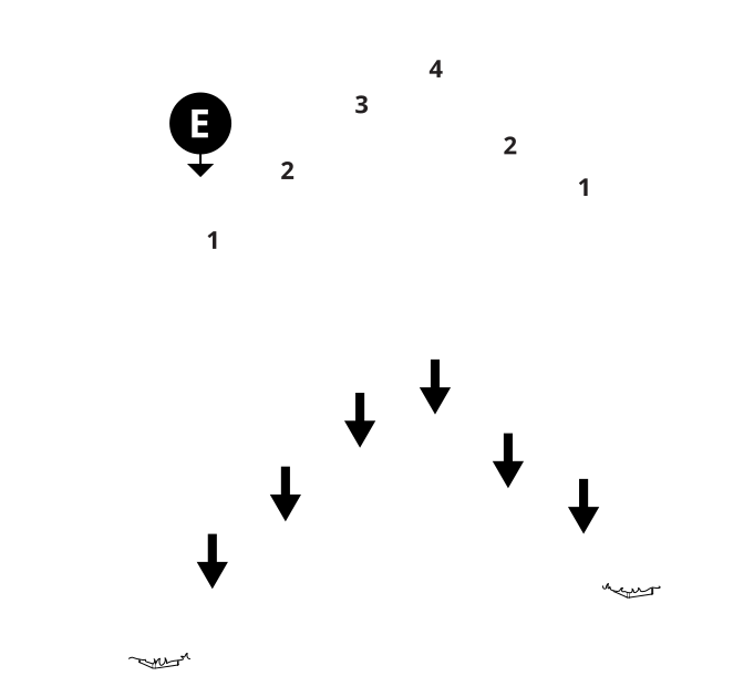
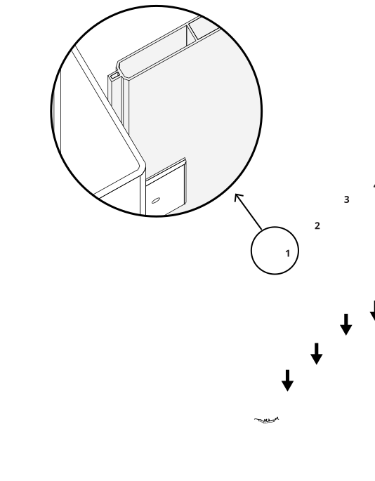
Install Boards (E) by sliding the outer boards through the brackets and channels first — the inner boards link together with their own track system. Insert outer boards first and middle boards last for the easiest install; ensure the outer boards are pushed to the back of the track.

Step 14: Top Rail
Parts Required
D x1 G x4
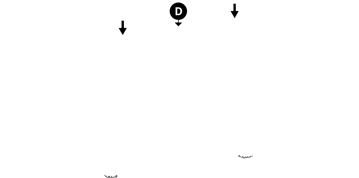
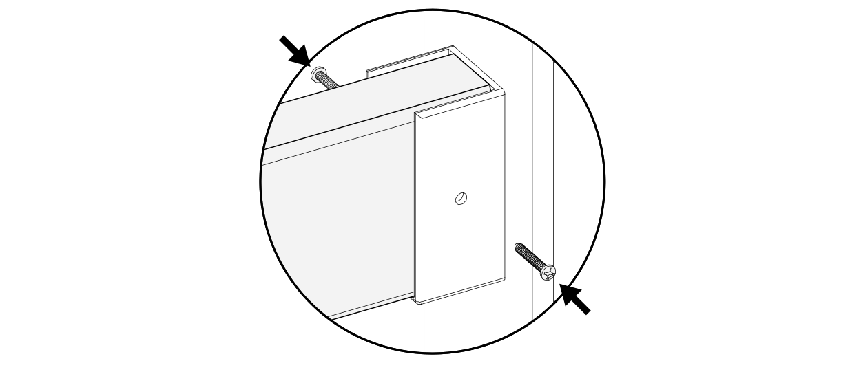
Install the top Rail (D) and secure with 4 screws (G) through the pre-drilled holes in the rail brackets.
Step 15: Post Caps
Parts Required
H x2
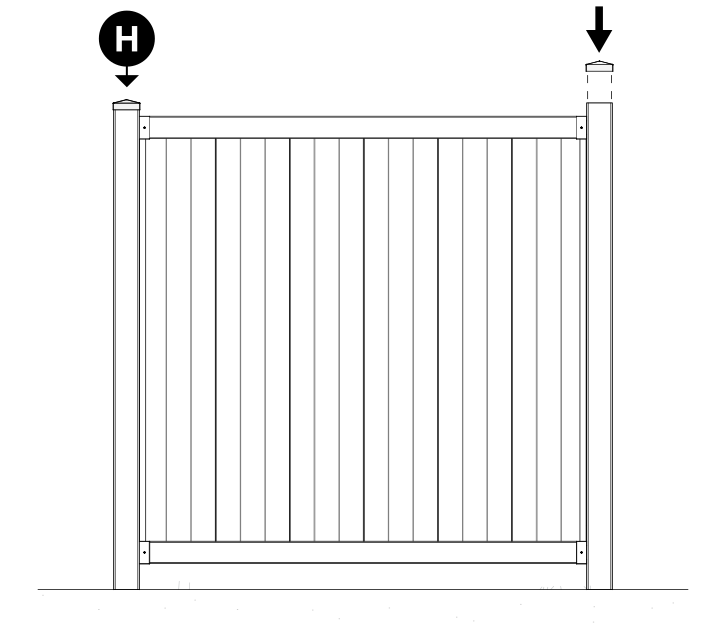
Trim down the tops of the posts if necessary, then install Post Caps (H).
Step 16 (Optional): Reinforce for High Wind
Parts Required
G x4
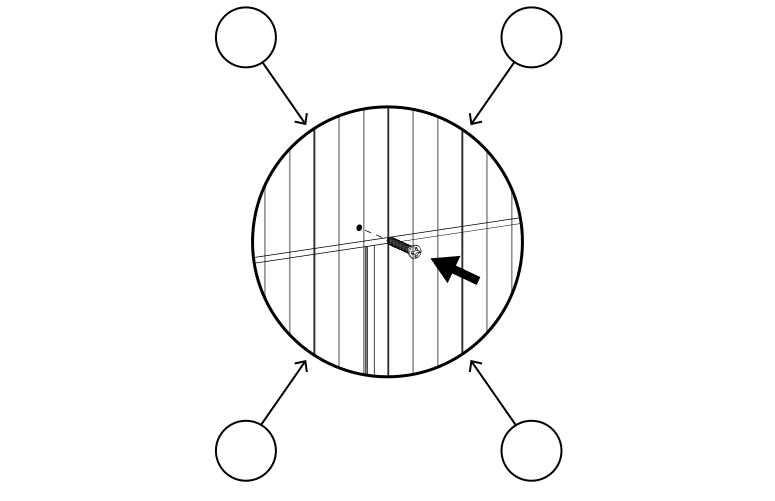
In high-wind applications, drive the 4 remaining screws (G) into the top and bottom rails to further secure the panel.
Need Help?
- Email: hmmm@wambamfence.com
- Phone: 704-892-5222 or 877-778-5733
- Text: 980-580-6580
